On this page we will show you the electrical work involved in replacing a Power One PVI 3.0 or 3.6 inverter with a Solis model supplied by us. By following these instructions a competent DIYer with basic tools will be able to replace their Power One inverter. You’re going to need some good quality insulated electricians screwdrivers, an insulated wire cutter/stripper, a combi drill and the appropriate fixings for the type of wall the inverter is fixed to.
Disclaimer: Note that for reasons of electrical safety we would encourage you to use a qualified electrician to perform the replacement if you are not 100% confident and competent. RED Electrical cannot accept any responsibility for any injuries or damage howsoever caused.
Please read through and understand the entire process before starting and make sure that you are comfortable with the steps before picking up any tools.
Many electricians are wary of getting involved in unfamiliar work. If yours is, show them this page and they will probably be happy to do the work for you. The process takes no more than half an hour.
If you have bought your replacement inverter from us then by all means give us a call if you’re at all unsure of any aspect of this process, or if anything does not go 100% to plan.
Step One – isolate the inverter
Firstly, you need to switch off the inverter using the isolators adjacent to it.
Click the video to the right to show this process.
Switch off the a.c. isolator first (red handle) then the d.c. isolator(s) (black handle). On some installations the d.c. isolator is built into the inverter (on the underside next to the d.c. connections).
IF ANY D.C. ISOLATOR HAS A RED HANDLE THEN IT IS PROBABLY AN A.C. ISOLATOR AND IS NOT SUITABLE FOR USE AS A D.C. ISOLATOR. IF THIS IS THE CASE THEN DO NOT PROCEED. GIVE US A CALL.
N.B. If your installation does not have both a.c. and d.c. isolators then do not proceed as it is not possible to safely isolate the inverter. Give us a call for advice if you’re unsure.
Once you have switched off the isolators, the capacitors inside the inverter will begin to discharge. The inverter display will go blank after a few seconds. Please allow 5 minutes before proceeding to the next step to allow the internal capacitors in the inverter to discharge.
Step 2 – unplug the d.c. connectors
The solar panels are connected to the inverter using four MC4 connectors. These are the black plugs and sockets to the left on the underside of the inverter.
Click the video to the right to show this process.
Remove the connectors by pinching the prongs and withdrawing the plugs. You may be able to pinch the prongs with your fingers, or you may need to use an appropriate tool to pinch them.
Do NOT attempt to unscrew the glands on the connectors. Only pull the connectors to withdraw them. Do NOT pull the connectors out using the cable.
Test the connectors are fitted on the cables correctly by GENTLY pulling the cables. If any come off then they are not fitted properly. MC4 connectors need to be fitted using a particular type of crimp tool. These are available on eBay for around £20, or we can make you some cables with connectors on them that you can connect to the d.c. isolators. Give us a call. Do NOT attempt to fit MC4 connectors with pliers, badly fitted MC4s are a fire hazard.
Step 3 – remove the inverter lower cover
You will need a Torx TX20 screwdriver or bit to do this. Unscrew the four screws securing the lower front cover to the inverter and remove the cover.
This will reveal the a.c. connection of the inverter.
Step 4 – Prove the a.c. supply is isolated
We now need to prove the a.c. supply to the inverter is dead BEFORE we disconnect it.
PROVE DEAD – STAY ALIVE.
Your inverter may have a protective cover over the a.c. terminal block. If so you will need to remove it using a flat insulated electricians screwdriver.
You need a voltage indicator for this. I use a Fluke T5 but any good quality mains voltage indicator will do.
This may seem odd but the first thing we’re going to do is switch the a.c. isolator on. This is so that we can put our test probes on the a.c. connections to prove that the voltage indicator is serviceable.
Once we see the mains voltage on the indicator, switch off the a.c. isolator again. You should be able to observe the mains voltage fall to zero.
Only if you have confirmed that the a.c. is dead using the above steps must you proceed to disconnect the a.c. cable from the inverter using a flat insulated electricians screwdriver.
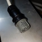
Step 5 – fit the new a.c. connector
Your Solis inverter includes an a.c. connector which will need to be put onto the free end of the a.c. cable. This is in a plastic bag underneath the new inverter.
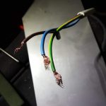
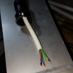
The wires coming from the a.c. cable are probably too long to fit within the new connector. We recommend shortening them to approximately 30mm each. Carefully strip the ends without damaging the conductor strands. If the a.c. cable is a twin and earth type then we recommend changing it to a flexible type of cable. You may wish to get an electrician to do this for you.
Firstly put the connector outer housing over the end of the cable.
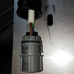
You will need a pozidrive PZ1 screwdriver to put the a.c. connector onto the end of the cable. Pay attention to the markings on the connector ‘L’, ‘N’ and ‘E’. If I need to explain the colours then you should get an electrician to do this job.
Once the cable is securely connected, push the outer housing over the connector (it only goes on one way) until it securely clicks, then tighten the compression gland by hand as far as it will go. Do not use a tool for this.
The entire process is depicted below:
Step 6 – change the inverter over
If you’ve got this far then all the electrical work is done.
The next stage is to remove the Power One inverter from the wall. It is secured to its wall bracket by a PH3 screw at the bottom. Remove the inverter and bracket (caution: the inverter weighs 18kg, make sure you have a firm hold of it).
Fasten the supplied Solis inverter bracket to the wall paying attention to where the inverter hangs on it. You don’t want it to get in the way of any connectors etc, and you do want to leave adequate ventilation space at the top of the inverter. The required clearances are in the inverter handbook.
Hang up the new inverter and put in the fixing screws on either side to secure it.
Finally, plug in the inverter and you’re done. If there is adequate solar irradiance then the inverter will start itself up. You don’t need to press any buttons or configure the inverter at all.
Note that there is no requirement to inform your FIT licensee, local authority, tennis partner or milkman that you have changed your inverter.